| Published in the July 2001 Issue of Anvil
Magazine
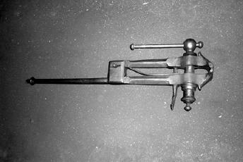
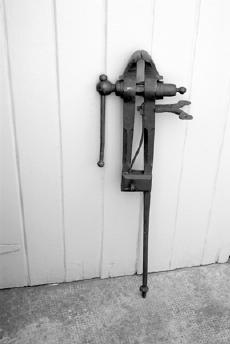
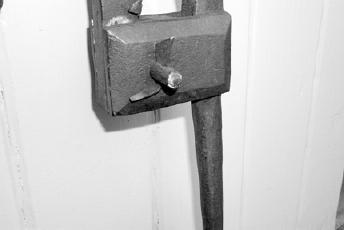
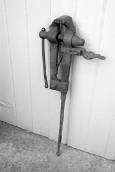
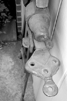
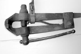
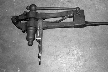
Note: Images and captions appear at the end of this article. Introduction Virtually every blacksmith and every collector of blacksmith tools has a leg vise or at least parts of one. These essential tools of the blacksmith trade, which come in all sizes, are commonly purchased used for a few dollars to a few hundred dollars, depending upon condition and size. This is amazing since most date from the 18th century to the early 20th century, with the vast majority dating before 1900. The survival and continuing use of these old leg vises attest to their excellent design and durable construction. Since most of the available used leg vises have been in service from 100 to 250 years, they obviously have suffered wear, damage and/or loss of parts. Many have been expediently repaired to keep them in service, while others have been set aside for parts or repair "someday." Over the past year, we have undertaken a project to understand the construction and proper restoration of 18th-and 19th-century leg vises. We have carefully studied surviving original leg vises and period documentation, and we have reverse-engineered how they were made. In our shop, we have hand forged, in the traditional manner, the parts commonly missing or damaged on early leg vises. The steps in making each part were carefully photo documented. This four-part, "How To" article, designed to assist those interested in restoring their leg vises, is written around the photographs. We have kept the text to a minimum. The photos with their descriptive captions will lead the reader through the actual restoration processes. Please note that only with the exception of springs, scrap wrought iron was used in making our parts. The originals were made of wrought iron, and we used wrought iron to better understand how the originals were made. However, that being said, mild steel can be used if wrought iron is not available or if mild steel is preferred. All of our heating and welding was done in a coal forge using out-of-the-box borax as a welding flux. A propane gas forge will also work if it is large enough; however, precise heat control and welding of heavy parts in a gas forge can be tricky. Further, please remember that we are presenting the restoration process. Stock and part dimensions will vary from vise to vise. Dimensions noted in the article are approximate only and will have to be adjusted so that the finished part looks proper and functions correctly on the individual vise being repaired. Each part is custom made and fitted. Basic Leg Vise Types Before making replacement parts for a vise, it is important to determine what the missing ones looked like. In keeping with our restoration approach, we made parts of the correct style, not simply ones that worked. While vises look alike, they have undergone many changes over the last 250 years, and their parts are not interchangeable. For simplicity, we have classified leg vises in three categories, early, middle, and late. The early period leg vises were most likely produced during the 18th and early 19th centuries. Figure I-01 is an almost complete example of an early vise. Note the decorative nature of the screw box and finely chamfered legs and cheeks on this early example. Figure I-02 is a transitional example probably from late in the early period. Here, the design of the screw box is simplified. The early vises are essentially all hand forged of wrought iron (with the exception of springs and jaw faces, which are high- carbon steel). They have mounting plates tenoned through the back leg of the vise and held fast with a wedge. The pivot pin (Fig. I-03) is likewise wedged in place. The screw boxes are composites of sheet and wrought iron brazed together. Leg vises of the middle period were made from the early to mid 19th-century. These vises are still mostly hand forged, but incorporate major design improvements. The mounting plates are secured with a wrap-around clamp instead of a tenon, and pivot pins are threaded for a nut. Solid wrought iron screw boxes have replaced the composite ones of the early period. Figure I-04 illustrates a fully developed example from the middle period. The late period covers from the middle of the 19th century through the early 20th century. However, big changes occurred in the late period as machine production replaced handwork. Cast iron and modern steels became the standard materials. While the basic design is recognizable (Fig. I-05), the parts are often die forged and even cast. This is usually visible in the form of flashing and mold parting lines as seen on the mounting plate edges in Figure I-06. This cast plate imitates a forged one beautifully. Also, as you can see in Figure I-05, the chamfers are gone from the vise legs and cheeks, and the screw box is cast and almost without decoration. The cast lead screw washers are cupped rather than flat (Figure I-07). You are most likely to find vises from this period in your travels. Frequently Encountered Problems and Jerry-Rigged Solutions The parts most commonly missing from leg vises are springs, jaw pivot pins with their wedges or nuts, lead screw washers, and mounting plate assemblies. Less commonly, lead screws and screw boxes are missing or damaged. Generally speaking, when these last two parts are missing altogether, the remainder of the vise is best used for parts, a lamp, or a boat anchor, unless you are willing to spend many hours in the restoration process. However, innovative and sometimes effective (though not necessarily correct) solutions are devised to extend the lives of the vises. Quick remedies for a missing spring include the smith's free hand to pull the vise open (i.e. nothing), a section of coil spring around the lead screw between the jaws, and a hacked-out piece of flat spring. Pivot pins are usually replaced with a bolt and nut. More imagination is often employed in the cases of lead screw washers, mounting plates, and screw boxes (Fig. I- 08). Replacement Springs We begin the restoration process with leg vise springs because they are frequently missing and fairly easy to make. At first glance, original leg vise springs appear straightforward, and they are. However, there are two subtleties. First, the end of the spring that bears against the moveable leg is usually folded over on itself to provide a smoother, longer-wearing bearing surface. Second, there is a distinct difference between the springs on early vises and those on the mid-19th to 20th century vises in how they are secured to the stationary leg (Figs. I-09 and I-10). These differences are detailed in the discussion that follows. Selecting proper stock of sufficient size is the initial step in making a vise spring. Any piece of good spring steel, such as a wagon, car, or trailer leaf spring or a heavy coil spring, will suffice. We used old leaf springs. In working with spring steel, be careful not to overheat and burn it. Generally, do not exceed an orange heat. First, heat the leaf spring in the forge and hot cut a blank roughly 10" long and a little wider than the width of the stationary leg. Alternatively, the spring blank can be forged rather than cut from spring stock. The following figures will take you through the process of forging and fitting an early-style vise spring. (Note that various stages in making two springs were photographed here to provide the best views of this process.) Hardening and tempering the spring is not necessary. Reheat the finished spring to a cherry red and place it on the side of the forge (not in the hot coals) to cool slowly. This is normalizing the spring, and it retains enough resilience to operate the vise jaw. Caution: Do not cool the spring quickly by quenching it. The spring will be brittle and will break when it is compressed. The process for fabricating a replacement spring for a mid-19th to 20th century leg vise is exactly the same except for hot punching the rectangular hole for the tenon of the mounting plate. The mounting plates on these later vises do not have tenons. Instead, they are fastened to the vise with a clamp around the stationary leg of the vise. Consequently, the tops of the springs are not punched but left straight or have a slight 90- degree lip (Fig. I-21). This clamp also secures the vise spring in position (Fig. I-22). The clamp method is a major structural improvement over the delicate tenon inserted through a mortise punched in the stationary leg of the earlier vises. Failure of these tenons is the primary reason for the loss of the spring and mounting plate on many of the early vises. Lead Screw Washers While the washer on the lead screw is one of the simplest pieces on the vise, it is quite important. Without this washer, the lead screw will wear deeply into the front leg of the vise, so it is essential that the washer is present and doing its job properly. A replacement for a missing washer can be easily made. Here is our process for making a forged example typical of those found on vises from the early and middle periods: Making a cast iron washer for a late period vise is foundry work and beyond the scope of this article. However, by following the forging process and then cupping one side of the washer to match Figure I-7, a suitable replacement for a cast example can be made. In Part II of this four-part article, we will take you through the process of making the early period mounting plates and pivot pins. |
|
| Figure I-01 - Early period leg vise. |
|
| Figure I-02 - Transitional early period vise. |
|
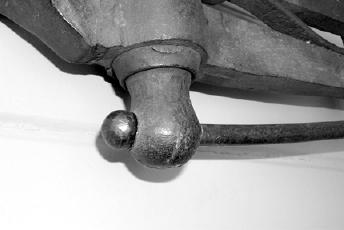
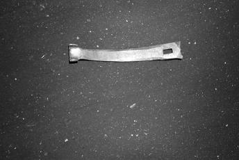
| Figure I-03 - Early period pivot pin and wedge. |
|
| Figure I-04 - Middle period leg vise. | Sorry, Missing Image |
| Figure I-05 - Late period leg vise. |
|
| Figure I-06 - Cast mounting plate. |
|
| Figure I-07 - Cast lead screw washer. |
|
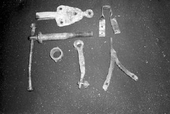
| Figure I-08 - Jerry-rigged replacement parts (clockwise from top): attempt at 19th. century-style mounting plate; twisted steel bar stock used for mounting vise; rough 18th century-style mounting wings; screw box made from a large wrought iron hinge pintle; wagon axle bushing used as a lead screw washer; lead screw made from a large shackle pin with welded bolt threads and a long bolt and nut for a T-handle. |
|
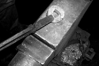
| Figure I-09 - Spring attachment on an 18th century vise. |
|
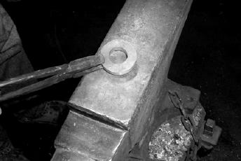
| Figure I-10 - Spring attachment on a late 19th century vise. |
|
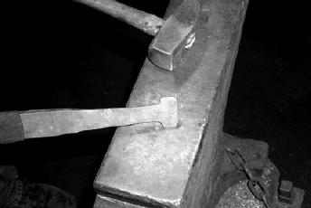
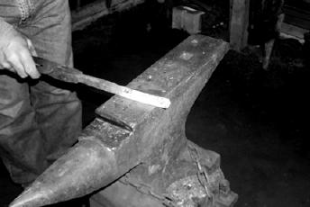
| Figure I-11 - Heat the spring blank and forge to the shape shown. At this point, the left portion of the blank is forged to a thickness of roughly 1/4" and a width the same width as the stationary leg of the vise. The right portion is tapered and thinned, and the end is flared ready for folding. |
|
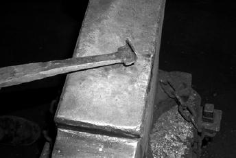
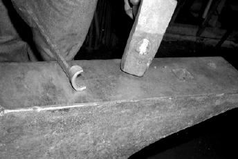
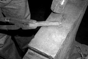
| Figure I-12 - Here the flared end of the spring is being folded back on itself. Note the thinness of this end of the spring. |
|
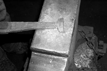
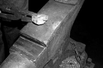
| Figure I-13 - The fold is complete and ready to be shaped into the bearing end of the spring. |
|
| Figure I-14 - The spring's bearing end is now rough forged to fit around the bottom section of the moveable leg. Final shaping of the bearing end is gently done hot over the actual vise leg using a light hammer. Be careful not to damage the vise leg. Thus formed, the harder steel spring will impart little wear on the softer iron vise leg. |
|
| Figure I-15 - Back view of the finished bearing end of the spring, showing the fold. |
|
| Figure I-16 - Front view of the finished bearing end of the spring showing the lips that were hot shaped to fit around the moveable leg of the vise. |
|
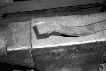
| Figure I-17 - Reheat the spring and bend it to the approximate shape required to open the moveable leg of the vise when the lead screw is loosened. Place the spring in position on the vise and mark it for cutting to length. |
|
| Figure I-18 - Hot cut the spring to length. Hot punch the rectangular hole to accept the tenon of the mounting plate. Chamfer the edges and dress the top of the spring. |
|
| Figure I-19 - Attach the spring to the vise and determine what adjustments need to be made to the spring shape for it to function properly. Remove the spring, reheat it and make the final adjustments. |
|
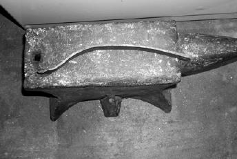
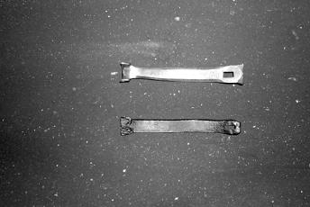
| Figure I-20 - Finished spring (above) shown next to the jerry-rigged example it replaced. |
|
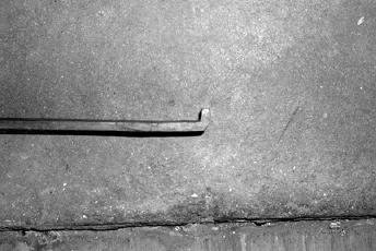
| Figure I-21 - Slight lip turned on top of springs for mid-19th to 20th century vises. |
|
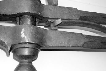
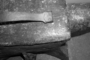
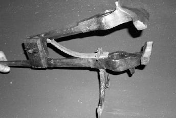
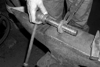
| Figure I-22 - Mid-19th century leg vise with clamp and wedge system for securing the spring and the mounting plate. |
|
| Figure I-23 - Forged washers are usually flat and made from bar stock instead of being cut from plate. A piece of wrought iron is drawn to size, approximately 1/2" square in this case. It is much easier to bend a square bar into a tight circle than a flat bar on edge, so the washer is made from square material and flattened after welding. The finished washer should be around 3/8" thick. |
|
| Figure I-24 - There are several ways to estimate the length of bar needed to make the correct diameter washer. We multiply the diameter of the lead screw by Pi (3.14) to calculate the circumference. We then add three times the thickness of the bar to the circumference for the bar length. The ends of the bar are upset and scarfed for welding. |
|
| Figure I-25 - Begin bending at the ends. Use a high heat and bend as tightly as you can. Once both ends are done, the middle is relatively easy to finish. |
|
| Figure I-26 - The washer is bent and ready for welding. Notice how the scarfed ends are thicker than the rest of the ring. |
|
| Figure I-27 - Another view of the washer before welding. At this stage, it is more important to align the scarfs properly than to worry about making a perfectly round ring. The hole can be trued during welding and cleanup. It will also stretch a bit, so the hole seems small at this stage. |
|
| Figure I-28 - This is the washer after welding and fine-tuning. It is flat and fairly uniform in thickness. The hole diameter should not change very much while flattening, but it is a good idea to keep everything a little under size until last. |
|
| Figure I-29 - Here, the washer is tested for fit on the screw. It should be snug. It is better to file a little inside the hole than to forge the piece oversize. |
|
| Stay tuned for part 2! | |
| Return to the July 2001 Table of Contents | |